X ray focal spot
X Ray Focal Spot. Means a spot width in the range of 0,1mm to 0,15mm (100µm to 150µm) in width and length. It follows that those radiographic characters which are influenced by focal spot size, namely, sharpness of shadow and the radiability of fine objects, are also variable. First of all, let’s understand the focal spot size. Please note that for other spot sizes the width and the length have different ranges.
 Effect of Focal Spot on Resolution (Contact Radiograph) Radiology From upstate.edu
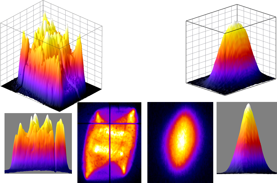
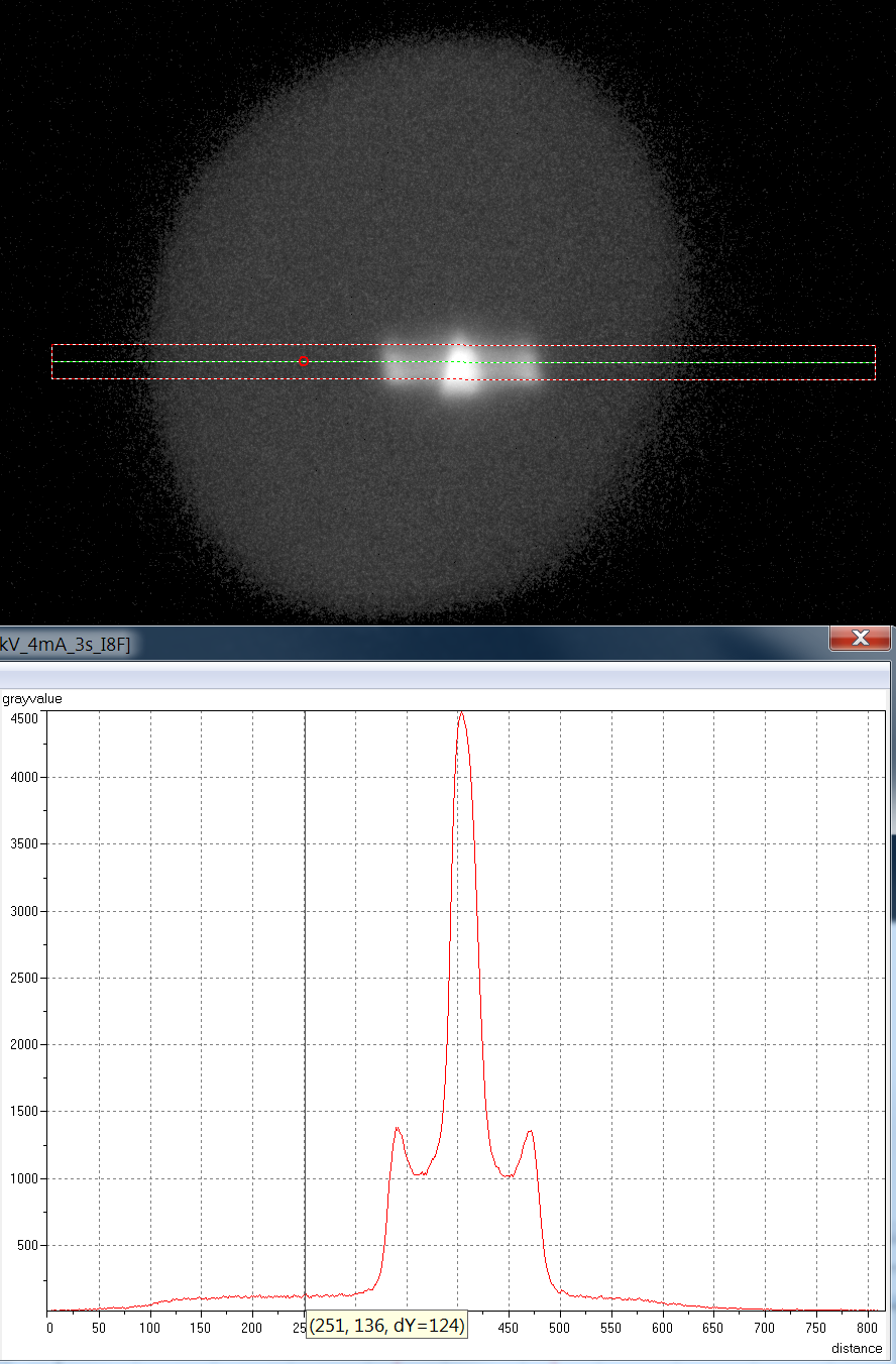
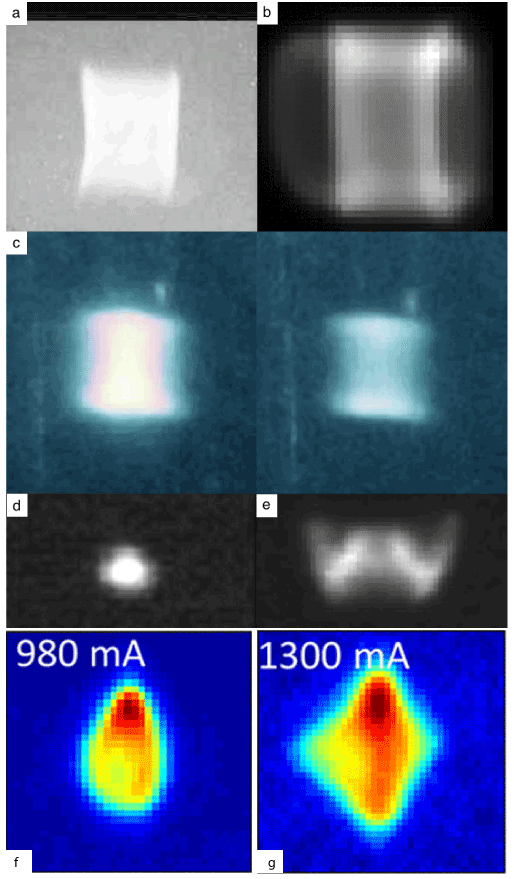
Focal spot in an x ray tube Therefore, the shape of the focal spot cannot be neglected, even if the shape distribution is not required by any standard practice. It affects the definition of the final imaging together with the flat panel detector. Two focal spot sizes were used (25 and 50 μm; A small focal spot is used when spatial resolution is important, while a large focal spot is employed when a short exposure time is the priority. Magnified radiographic images of the star test pattern yield information on the energy distribution in the focal spot allowing determination of the effective focal spot size,.
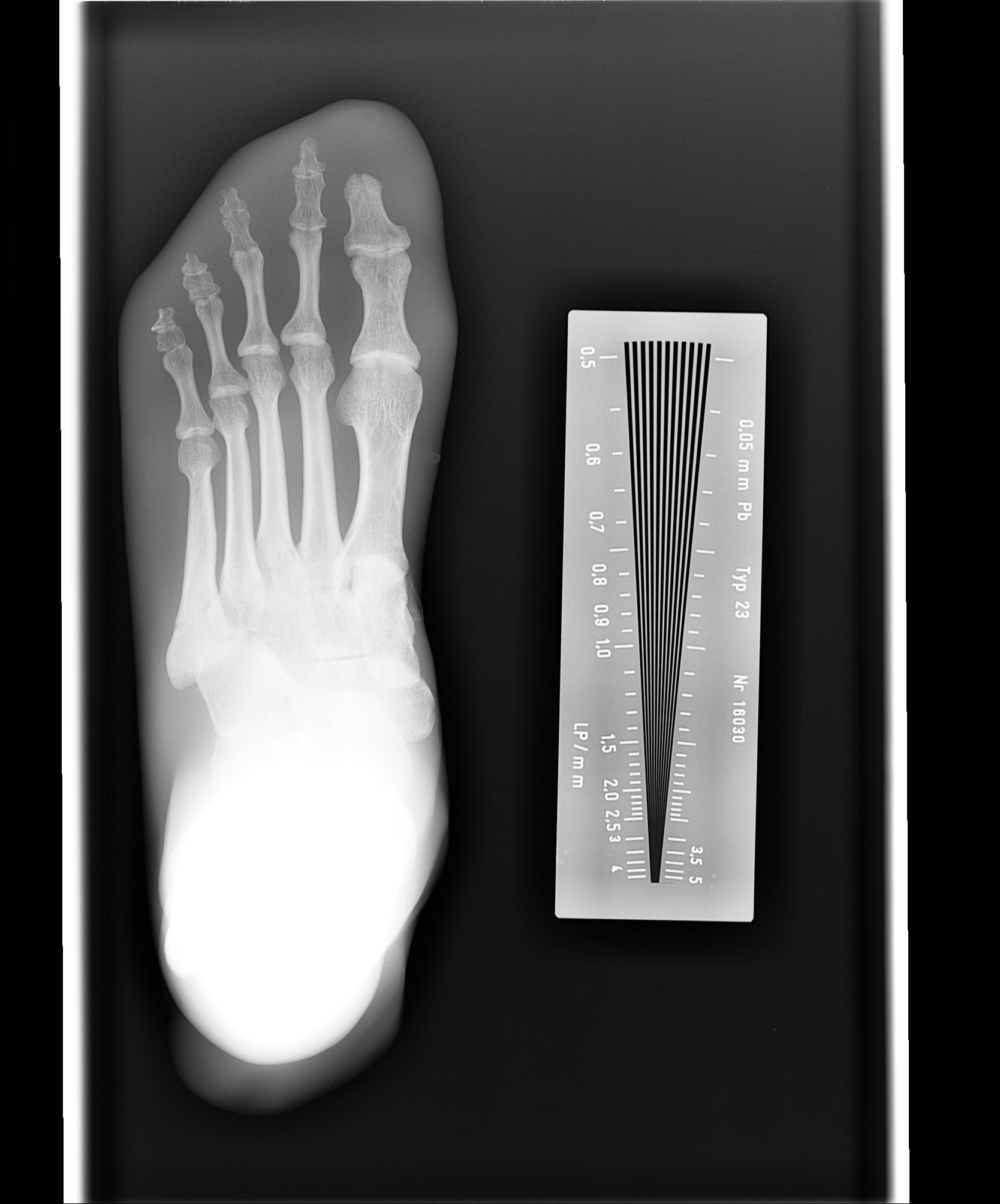
The limiting spatial resolution is essentially the same (i.e., ~3 lp/mm) that was achieved using the small focal spot.
This variable only affects recorded detail. The effective focal length of a focal spot can be calculated. Nuclear instruments and methods in physics research section b: Please note that for other spot sizes the width and the length have different ranges. It affects the definition of the final imaging together with the flat panel detector. The filament that acts as the cathode emits.
 Source: x-ray-forum.net
Please note that for other spot sizes the width and the length have different ranges. National center for biotechnology information The most common device providing an image of. Means a spot width in the range of 0,1mm to 0,15mm (100µm to 150µm) in width and length. It follows that those radiographic characters which are influenced by focal spot size, namely, sharpness of shadow and the radiability of fine objects, are also variable.
 Source: well-man.com
The smaller the focal spot, the sharper the recorded detail or the more recorded detail increases. This is a 41 × 41 pixel image with pixel size of 0.05 mm per dimension. Lengthy exposure times can reduce workflow and limit the number of applications where. The focal spot sizes commonly employed are: Beam interactions with materials and atoms, vol.
 Source: miac.unibas.ch
This method is less complicated than the pinhole or slit camera process and assuming an approximately ideal intensity distribution in the focal spot, it is in many cases. First of all, let’s understand the focal spot size. Please note that for other spot sizes the width and the length have different ranges. A spot view (also known as a spot compression view or focal compression view) is an additional mammographic view performed by applying the compression to a smaller area of tissue using a small compression paddle, increasing the effective pressure on that spot. Magnified radiographic images of the star test pattern yield information on the energy distribution in the focal spot allowing determination of the effective focal spot size,.
 Source: upstate.edu
Look at the image at right for a visual representation. A transparent bladder was used to applied weld pressure. Means a spot width in the range of 0,1mm to 0,15mm (100µm to 150µm) in width and length. The modulation transfer functions (mtfs) and line spread functions (lsfs) were also determined. Please note that for other spot sizes the width and the length have different ranges.
 Source: youtube.com
This variable only affects recorded detail. It follows that those radiographic characters which are influenced by focal spot size, namely, sharpness of shadow and the radiability of fine objects, are also variable. The filament that acts as the cathode emits. A transparent bladder was used to applied weld pressure. The modulation transfer functions (mtfs) and line spread functions (lsfs) were also determined.
 Source: pinterest.co.uk
Learn about the focal spot and the line focus principle. Beam interactions with materials and atoms, vol. The filament that acts as the cathode emits. Magnified radiographic images of the star test pattern yield information on the energy distribution in the focal spot allowing determination of the effective focal spot size,. In the case of the small focal spot for pxs evo, the focal spot is reduced from 3.0 mm to 1.0 mm and the geometric unsharpness is reduced by a factor of three.
 Source: dentalcare.com
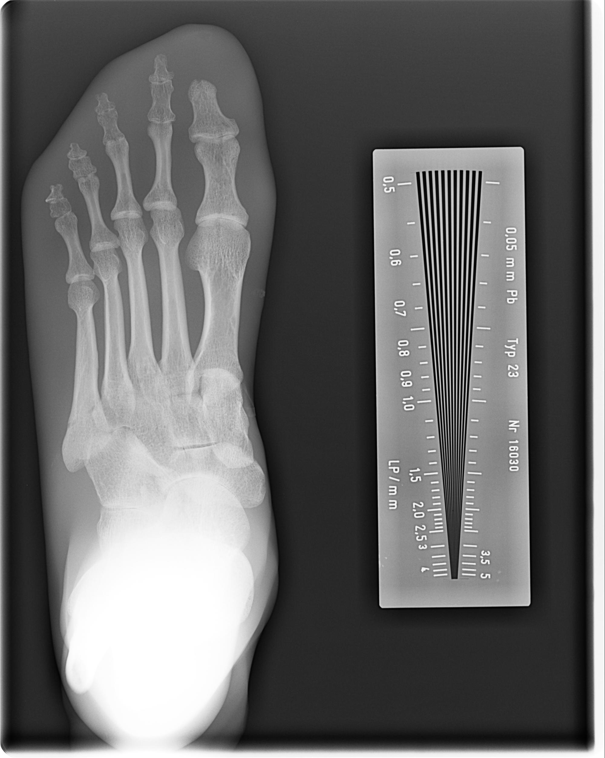
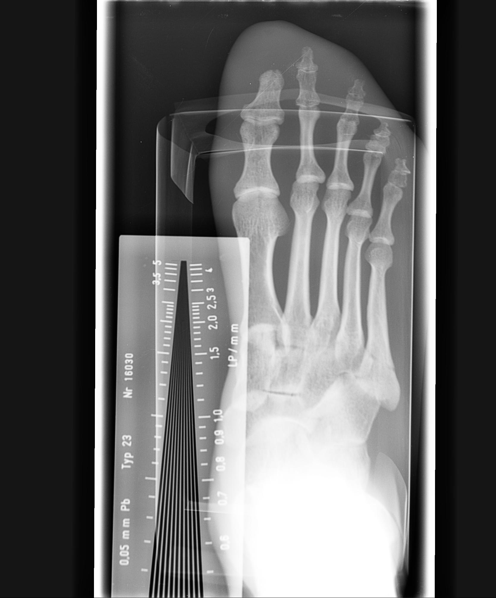
The radiograph shown above was taken using the same techniques (kv/mas), and the identical (contact) irradiation geometry, but this time employing the large focal spot size of 1.2 mm. 0.3 mm and 0.6 mm, usually for mammography; The focal spot sizes commonly employed are: A transparent bladder was used to applied weld pressure. Beam interactions with materials and atoms, vol.
 Source: upstate.edu
The radiograph shown above was taken using the same techniques (kv/mas), and the identical (contact) irradiation geometry, but this time employing the large focal spot size of 1.2 mm. First of all, let’s understand the focal spot size. 0.3 mm and 0.6 mm, usually for mammography; Two focal spot sizes were used (25 and 50 μm; Look at the image at right for a visual representation.
 Source: x-ray-forum.net
In fact, the measurement of such size is recognized to be of primary importance during acceptance tests and image quality evaluations of clinical radiography systems. Magnified radiographic images of the star test pattern yield information on the energy distribution in the focal spot allowing determination of the effective focal spot size,. The star pattern focal spot sizes agreed with the effective sizes calculated from. The smaller the focal spot, the sharper the recorded detail or the more recorded detail increases. National center for biotechnology information
 Source: upstate.edu
The star pattern focal spot sizes agreed with the effective sizes calculated from. A transparent bladder was used to applied weld pressure. A small focal spot is used when spatial resolution is important, while a large focal spot is employed when a short exposure time is the priority. It follows that those radiographic characters which are influenced by focal spot size, namely, sharpness of shadow and the radiability of fine objects, are also variable. 0.3 mm and 0.6 mm, usually for mammography;
 Source: oatext.com
Magnified radiographic images of the star test pattern yield information on the energy distribution in the focal spot allowing determination of the effective focal spot size,. The effective focal length of a focal spot can be calculated. A small focal spot is used when spatial resolution is important, while a large focal spot is employed when a short exposure time is the priority. It follows that those radiographic characters which are influenced by focal spot size, namely, sharpness of shadow and the radiability of fine objects, are also variable. This variable only affects recorded detail.
 Source: cureus.com
The radiograph shown above was taken using the same techniques (kv/mas), and the identical (contact) irradiation geometry, but this time employing the large focal spot size of 1.2 mm. The most common device providing an image of. A transparent bladder was used to applied weld pressure. The modulation transfer functions (mtfs) and line spread functions (lsfs) were also determined. The smaller the focal spot, the sharper the recorded detail or the more recorded detail increases.
 Source: upstate.edu
1.0 mm and 1.2 mm, usually for general radiography; Look at the image at right for a visual representation. A transparent bladder was used to applied weld pressure. 0.3 mm and 0.6 mm, usually for mammography; This variable only affects recorded detail.
 Source: youtube.com
The focal spot sizes commonly employed are: First of all, let’s understand the focal spot size. The smaller the focal spot, the sharper the recorded detail or the more recorded detail increases. Nuclear instruments and methods in physics research section b: A small focal spot is used when spatial resolution is important, while a large focal spot is employed when a short exposure time is the priority.
 Source: osseozone.com
Means a spot width in the range of 0,1mm to 0,15mm (100µm to 150µm) in width and length. The smaller the focal spot, the sharper the recorded detail or the more recorded detail increases. The most common device providing an image of. In fact, the measurement of such size is recognized to be of primary importance during acceptance tests and image quality evaluations of clinical radiography systems. It affects the definition of the final imaging together with the flat panel detector.
 Source: pinterest.com
Beam interactions with materials and atoms, vol. National center for biotechnology information The modulation transfer functions (mtfs) and line spread functions (lsfs) were also determined. A small focal spot is used when spatial resolution is important, while a large focal spot is employed when a short exposure time is the priority. This method is less complicated than the pinhole or slit camera process and assuming an approximately ideal intensity distribution in the focal spot, it is in many cases.
 Source: researchgate.net
This is a 41 × 41 pixel image with pixel size of 0.05 mm per dimension. The limiting spatial resolution is essentially the same (i.e., ~3 lp/mm) that was achieved using the small focal spot. Focal spot in an x ray tube A transparent bladder was used to applied weld pressure. National center for biotechnology information
 Source: researchgate.net
Beam interactions with materials and atoms, vol. Means a spot width in the range of 0,1mm to 0,15mm (100µm to 150µm) in width and length. It follows that those radiographic characters which are influenced by focal spot size, namely, sharpness of shadow and the radiability of fine objects, are also variable. This method is less complicated than the pinhole or slit camera process and assuming an approximately ideal intensity distribution in the focal spot, it is in many cases. The limiting spatial resolution is essentially the same (i.e., ~3 lp/mm) that was achieved using the small focal spot.
If you find this site convienient, please support us by sharing this posts to your favorite social media accounts like Facebook, Instagram and so on or you can also bookmark this blog page with the title x ray focal spot by using Ctrl + D for devices a laptop with a Windows operating system or Command + D for laptops with an Apple operating system. If you use a smartphone, you can also use the drawer menu of the browser you are using. Whether it’s a Windows, Mac, iOS or Android operating system, you will still be able to bookmark this website.

